
Raising the Mast of a Small Sailboat with The Resourceful Sailor — The Solo Version
It’s been a while since we’ve heard from The Resourceful Sailor. Since he lowered the mast on his boat Sampaguita last June, he’s been busy taking care of several boat projects. Now he’s back on deck and has sent us this detailed report on raising the mast.
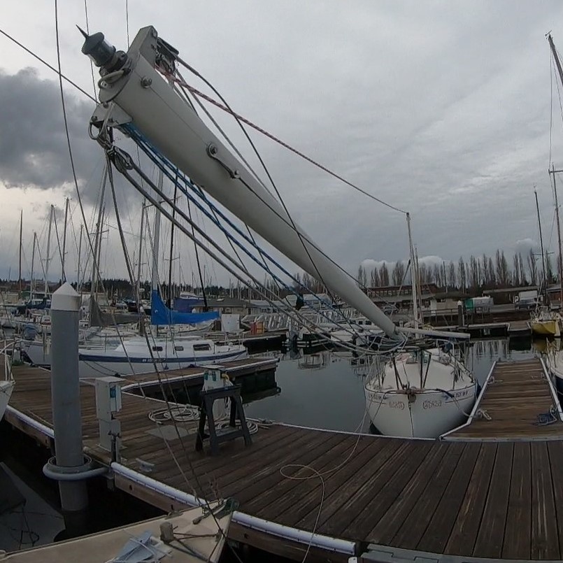
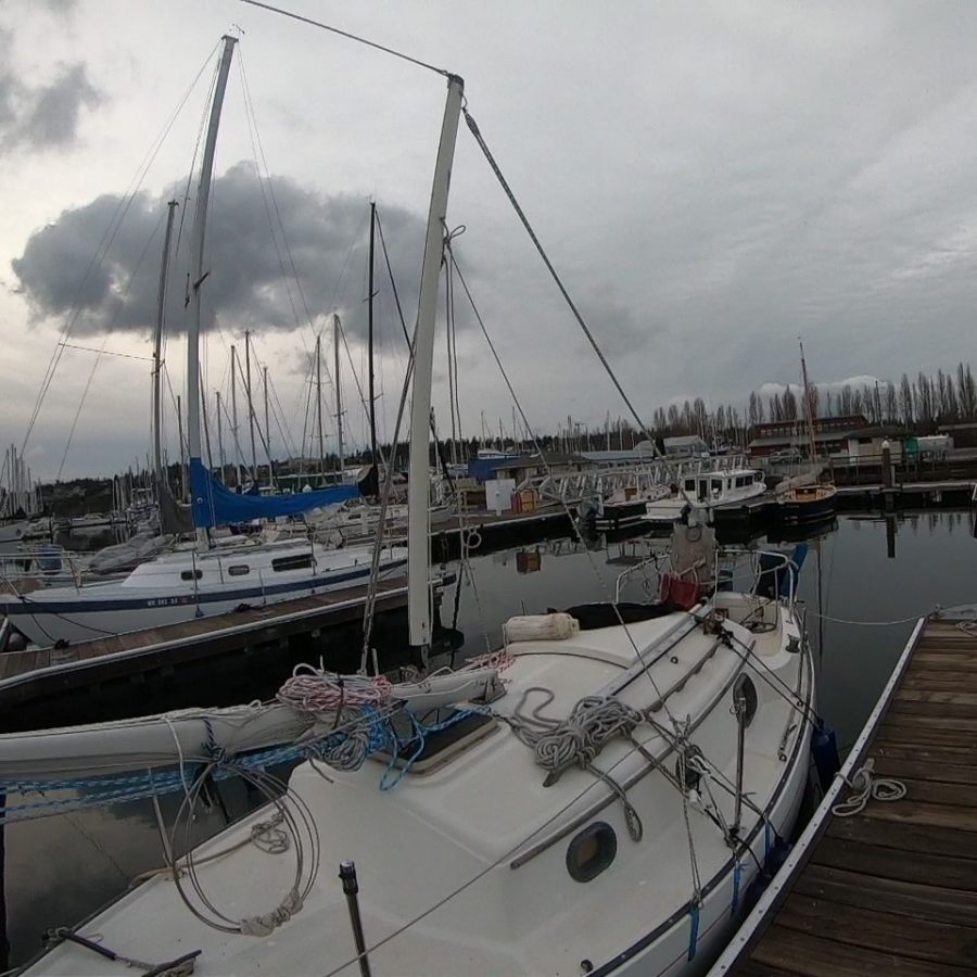
What goes down must go up? After a rig refit, the mast of Sampaguita, a Pacific Seacraft Flicka 20, was ready to be raised. Still in her Port Townsend slip, the process was, generally, the opposite of lowering, presented in ‘Lectronic Latitude on June 16, 2021 — Lowering the Mast on a Small Sailboat with The Resourceful Sailor.
It required the same bridle setup. The boom, again, would act as a gin pole to gain the proper angle for leverage. The mainsheet block and tackle would do the heavy lifting. Rather than write the same thing again, I will focus on the differences between the two procedures and provide some previously left-out insights. In doing this, I will presume that you have read or will review the installment mentioned above.
For raising, only the cap shrouds and the headstay needed to be attached to their respective chainplates. Out of respect for Murphy’s Law, the other wires were secured tightly to the mast to mitigate their inclination to get snagged. Snagged wires like to kink, and whether new or old, it is unsatisfying, not to mention detrimental to their longevity and strength. The turnbuckles were wrapped in rags and secured to the mast, preventing them from scratching and banging into anything (everything.)
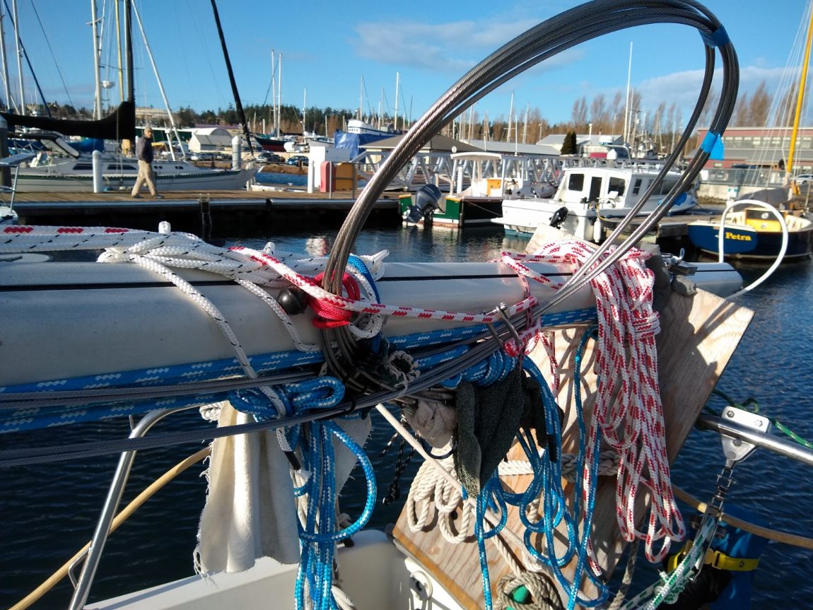
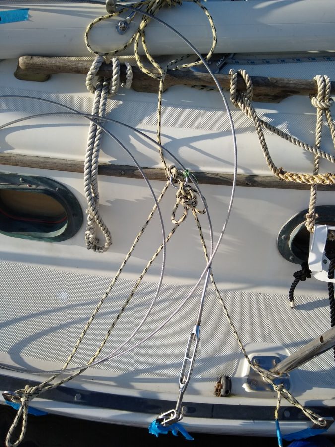
The bridle setup was more challenging to organize with the rig down than up. Since I had new wires, I needed to re-seize the stainless steel rings to the cap shrouds. It required holding up the wire to determine the proper pivot points with the mast. Then the opposing force lines to the lower stay chainplates were added, conceptualizing the rigid triangle necessary to maintain the pivot points. With the rig up, it is easier to build and see this. But down, it is a floppy mess. Then, a line was attached to each ring, ready to lead to a bail on the boom. A block and tackle served nicely for this on one side for ease of adjustment. These guylines will provide the opposing forces to keep the boom centered.
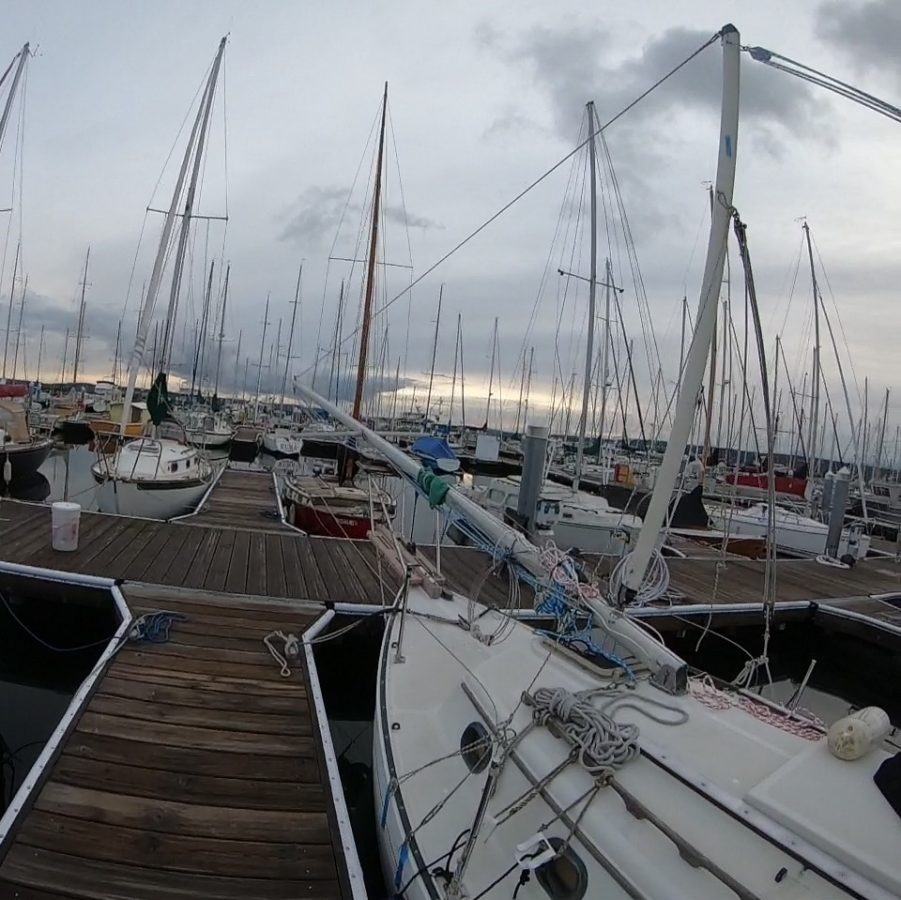
After that, I moved the mast to the tabernacle and pinned its base in the ready position. A final review of the halyard and wire leads and spreader orientations was done. A reminder: Always be on the lookout for snagging wires and lines whenever you move the mast.
The boom, as a gin pole, could then be added. When lowering, it was already in position and there was only the matter of attaching the bridle lines. However, with the mast down, the boom would be attached starting in a vertical position, which involved some boat yoga. I shackled the mainsheet and topping lift to its outer end. Lots of slack was fed into those lines, allowing for lifting it straight up. While holding it so, I pinned the mast end to the gooseneck. I picked up the previously-led guylines (the line and the block and tackle) and attached them to the boom bail. I tightened and adjusted the mainsheet, the topping lift, and the guylines until the boom was centered and vertical. The opposing forces held the gin pole in place.
With the correct bridle setup, the mast base in the tabernacle, and the gin pole in place, it was simply a matter of hoisting the mast. On a Flicka 20, the round bar traveler and the four-part mainsheet block and tackle are very accommodating to providing the mechanical advantage necessary for raising and lowering the mast. To a soloist, this advantage was indispensable. It took two hands and a bit of leaning to get it moving, but it became easier as it went higher. An eye was kept on the centerline alignment of the mast and boom, making sure the bridle prep was accurate, and watching that the wires did not snag.
The accompanying video shows the raising from a first-person view and solo. In contrast to lowering the mast, gravity is less of a friend, so the ascent is slower, with a bit more heave-ho. There is no shame in re-lowering the mast to adjust the bridle lines or sort out the wires. It is better to correct them early than to think something will be all right when it is not. Raising and lowering the mast is not rocket science, but 99% of the gig is proper preparation. If something goes wrong, it could be catastrophic, so double- and triple-check. It can be intimidating at first, but it is simple physics and simple tools at work. Remember, keep it safe and prudent, and have a blast.
This is so stressful to watch! I would have never had the courage to do it myself. As always, you have my respect and admiration. Well done!
Rusty, thanks for the kind words, and thanks for reading.
Joshua,
Thank you for taking the time for so nicely relaying your experiences on single-hand stepping the mast on your Flicka. I am currently refining this design process for my own boat, and am thus interested in the finer details. My initial questions are two:
First, concerning the method and material for seizing the bridle to the cap shrouds: As you state, a properly rigged bridle is key to making the process work. How did you analyze the adequacy of your seizing method and the loads that would be experienced?
Temporary seizing is a good place to start for me, but since I do this spring and fall every year, I have considered incorporating a more permanent nicropress and cable pigtail for the ring attachment (the loads there are not very high). A triangular plate in the top shroud with attachment points for the bridle connection points would be nicer, but more expensive to implement. Either way, it is probably prudent to use a temporary seizing first, to demonstrate dimensional functionality prior to a permanent solution.
Second, I am sure you release the cap shrouds to allow the bridle arrangement some up/down movement as a result of the mast butt movement in the tabernacle during stepping. Somehow I must have missed that. Once upon a time I tried raising the mast with very slack uppers (guessing at what was needed instead of graphical analysis or calculations) instead of the bridle approach (all else was like your scenario). Because the slack was inadequate and no bridle, I managed to bend my boom out of alignment. :o(. A good machine shop worked that out.
As long as the mast remains vertical through the lift, there isn’t much load on that ring connection, but its job is keeping the mast in a vertical/perpendicular orientation through the lift. But if some kind of unforeseen incident would create shock loading on the seized ring, (say even 2 pounds of lateral movement (force at the truck) that would correlate to about 56 foot-pounds of moment (engineering statics) applied at the ring due to the long lever arm of the mast. If it were 5 pounds force perpendicular at the top of the mast, it would correlate to up to 140 foot pounds. In my view, a shock load of 5 pounds or maybe more, isn’t an unlikely scenario, considering Murphy. I can’t think of a way to analyze the strength of the seizing, and prayer does not work for me. So, how did you analyze the adequacy of your seizing method and what did you use? Wire?
In my case, I have been stepping my mast at least annually, on my Lancer 25 for more than 35 years. I usually do it on the hard, or in the water if launching was via travel lift or something else that dictated the mast needed to be down when launched. But in at least one case, years ago, while sailing near Cowichan Bay at Vancouver Island, the jib wire jumped the sheave (a result of rough water and a slack line while dousing the jib) at the truck, and jammed along-side of the sheave when I tried to pull the sail down. I wasn’t sure of the problem at the time, but the sail definitely was not coming down, so I wrapped the jib halyard around the forestay to try to contain the partially-filled sail and considered my options. Luckily, upon checking my depth sounder, and found some shallow 30’ water (unheard of up there) and dropped the hook (probably on a rock bottom) and it held well enough for the task at hand. My mate always helped tail the line connected to the backstay at the winch and through a clam cleat to hold things if I needed a rest. I just loosened and released the rigging as necessary, muscle-dropped the mast and used the dinghy to go forward and sort things out. It was a very high reach, but I was successful. After I got the mast back up it started to rain….. I later drilled a hole in the truck to insert a stainless wire restraint, so the halyard cable could not be thrown off the sheave again.
I have toyed with analyzing more mechanical methods for raising the mast now that I am older, less strong, and my first mate has passed on. That is what piqued my interest on your article.
The Flicka is ready-made (Bingham designed it in; I am sure) for this raising procedure. The Flicka doesn’t have many complications, since there are double lowers in perfect position for the bridle attachment, and the cap shrouds are neatly centered to the mast. The Lancer is not so nice. It has a single set of lowers, and the chain plate has about 1” between the 2 connections for uppers and lowers. These are also set about 3” aft of mast centerline. The original Lancer design was a tabernacle (not exactly the proper technical term, but we will go with it) with the slot in the tabernacle tabs, and a through bolt for securing the mast. I would say this is the usual case for production trailer sailor boats. I have never been wild about the uneven up-and-down friction-prone mast butt action and the associated movement reflected in the rigging connections during stepping. I do have a strong toe rail to connect the bridle, but the chain-plate bridle connection will not work geometrically. I have purchased a hinged tabernacle plate from Ballinger Spars, which will smooth out the rotational process down there. However, the negative thing it does, is place the pivot point about 3” in front of the mast centerline. The hinge movement is forward of the mast (eccentric) and translates to about 3” up-and-down movement (tensioning or slacking) of the cap shroud/ bridle assembly while stepping the Lancer mast. With the eccentric hinged plate pivot, (while rotating up), the mast butt raises momentarily for about 1/4” (slackening the rigging) and then drops down 3” (requiring an equal amount of rigging slack or things will go into tension, which is no good). The shrouds or bridle assembly must allow a lengthening of 3” during rotation of the mast butt into final position (as determined by graphical analysis). On lowering, the movement is opposite, so the shrouds will slacken throughout rotation without causing any tension problems, and there is plenty of play being created to keep any stresses from developing. I suppose the key in my case is to set the bridle configuration when the mast I up, thus ‘dimensionally building in’ the 3” movement required into the bridle/shroud system. Thoughts?
The following is an analysis of the forces on the Lancer rigging dimensions and mast weight: The mast (Kenyon 3550) is 28’ long and weighs in at 62 pounds. I arbitrarily rounded to 70 pounds for these calculations. The moment to initiate lifting the mast is 980 foot pounds. (28’x half the mast length x70 pounds – assume equal weight distribution per foot.). That is to say, if the mast is on the ground and you lift one end, it will take 35 pounds force through a distance of 28 feet (=980 foot pounds of moment acting on the mast to lift one end off of the ground). But in raising the mast, the force is pulling more aft than up (requiring vector analysis which I will get to). I am currently considering a 10’ jibboom mounted at the hinge point and not higher on the mast where the boom lives, which changes the numbers- (no bending forces on the mast – which are not really great enough to mean much to the 3550). Also in the Flicka case, boom length (as with lancer) is probably about 8’. A 10’ jibboom lowers the forces more than an 8’, but using the existing spar is practical. It is probably prudent for me to reconsider and re-calculate using the boom in its usual position. A few years ago, I designed and had a fitting made to connect a jibboom to the mast foot, so I was considering using it.
So, running the numbers based on the Lacer backstay distance to the mast and initial lay of the mast, it would take (rounded) 103 pounds of tension in the backstay from the mast truck to the jibboom, and 125 pounds of tension from the jibboom to the backstay connection point. Compression loading in the 10’ boom is 114 pounds. Yes, one can use Eulers equation to analyze buckling forces, but I didn’t do it. Following good engineering practice with a factor of safety of at least 2, these numbers would be double the values shown for design checking of adequacy of rigging and spars. Confirming your experience, as the mast goes up, the center of gravity moves aft, requiring less and less force to raise the mast (and the geometry is changing) to increase efficiency of the forces as the mast goes up. 30degrees=858 ft lbs, 45 degrees=700 ft lbs, 70 degrees=350 ft lbs. 70 degrees into the lift, it would equate to 10 pounds of perpendicular force applied at the top (the center of mast mass has shifted to only 5’ in front of the final mast position). With a 4:1 ratio applied on the backstay, the pull on the line is about 31 pounds force for the Lancer System. The Flicka system is somewhat more (I don’t have the dimensions to analyze it), but from your description it was probably 40 pounds or less to start the raise, and then the tension required reduces as the mast goes up.
Since the pull for the lancer scenario calculates in at around 31 pounds, I am planning to run the bitter end of the 4:1 through a block at the stern, to the bow, through a blocks on the bow, and use the anchor windlass to pull the mast up (the windlass maximum has 400 pounds of tension available). So even with friction losses, there should be no issue. I have a windlass switch in the cockpit, and a second hand-held remote at the forward hatch. It is a very convenient setup for going forward and guiding the mast or sorting out issues.
Also, after my spouse passed, I put a winch at about 5’ high on the mast, and I ran the raising line there, instead of needing someone tailing at the cockpit. It is easier (almost necessary) to have a helper with me at the mast. I have lowered the mast alone with this manual system by taking wraps on the winch and playing out slack while catching the mast. However, without a jibboom, the forces are tougher to man-handle alone at the end of the lowering process.
Comments are appreciated, as there is always something else to be considered or learned. Thanks
Jim,
Thanks for reading and taking the time to engage. You have certainly been thinking about this! You get far deeper into the physics than I ever have and I suspect, many readers and sailors.
Regarding seizing the rings on, I don’t overthink it. I have some net twine and I wrap and figure-eight it until I am sure it is strong enough. They are not permanent installations but are easy for me to put on as needed. Thoughtful marlinspike would make a nice permanent install.
I have seen a different Flicka install that had the cap shroud turnbuckle placed at the pivot point. This removed the need for a seized-on ring and also gave a nice pivot point that does not bend the wire. Kinking the wire is my big concern, but the forces and the pivot point have not been high enough to do this, so without doing the physics calculation, the stress is low.
Regarding the extra slack in the cap shrouds to accommodate that extra lift that occurs as the mast tips forward, no, I did not mention it, but it is a thing. I learned of that when I did not have them slack enough on a lowering. I recognized what was happening, so rather than forcing it, I backed off, adjusted, and restarted. Article scope naturally means some things are left out. That is good intel on bending your boom though. I have found on a sailboat, that if something feels like it is not running free, something is wrong. I don’t force it.
Thanks for the reply, Joshua.
I am leaning toward installing a permanent 4-hole triangular plate in the cap shroud at the bridle connection. This would create clear movement for hinge point attachments, and address stresses that can occur there. The rest is just a matter of rigging things up.
Best wishes in the new year.